WELCOME ON BOARD
Ladies and gentlemen, welcome to what is possibly the most detailed and complete guide on how to calculate and solve wind problems in general navigation. If you have made it this far, it is very likely that you are a struggling student pilot or an instructor preparing tomorrow’s class. Whatever the reason, take a seat and get ready for a reading that we will try to make as enjoyable as possible.
This guide has been designed to be read step by step and includes explanatory videos. The guide loses its effect and magic if the videos are not watched as you progress through the reading.
WHY DO WE NEED TO KNOW HOW TO SOLVE WIND PROBLEMS?
Although nowadays there is software capable of calculating a wind-corrected route in just seconds, solving this type of exercise is still fundamental in the training of future pilots. Through them, you come to the understanding of the concepts of heading, track, true airspeed, groundspeed, wind and velocity. For this reason, these problems nowadays continue and will continue to be part of the written exams.
VECTORS
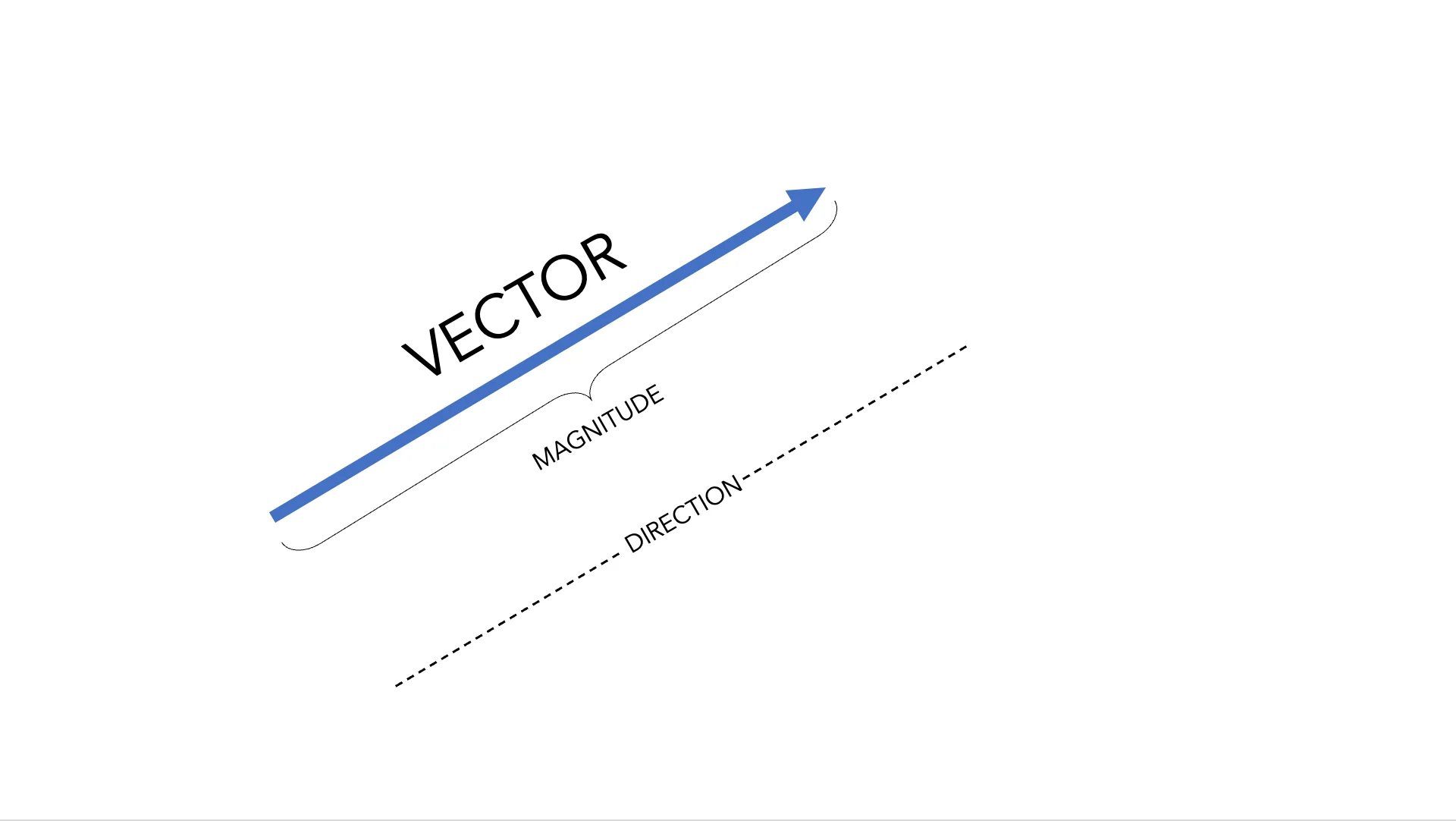
In physics there are quantities that can be described by a single value and its unit, called scalar quantities, such as mass (5 kg) or distance (100 m). However, other quantities require more information to be completely defined. An example is velocity. It needs a magnitude (size), and a direction. For this reason, velocity is a vector quantity and is represented by a vector.
VECTORS IN AIR NAVIGATION
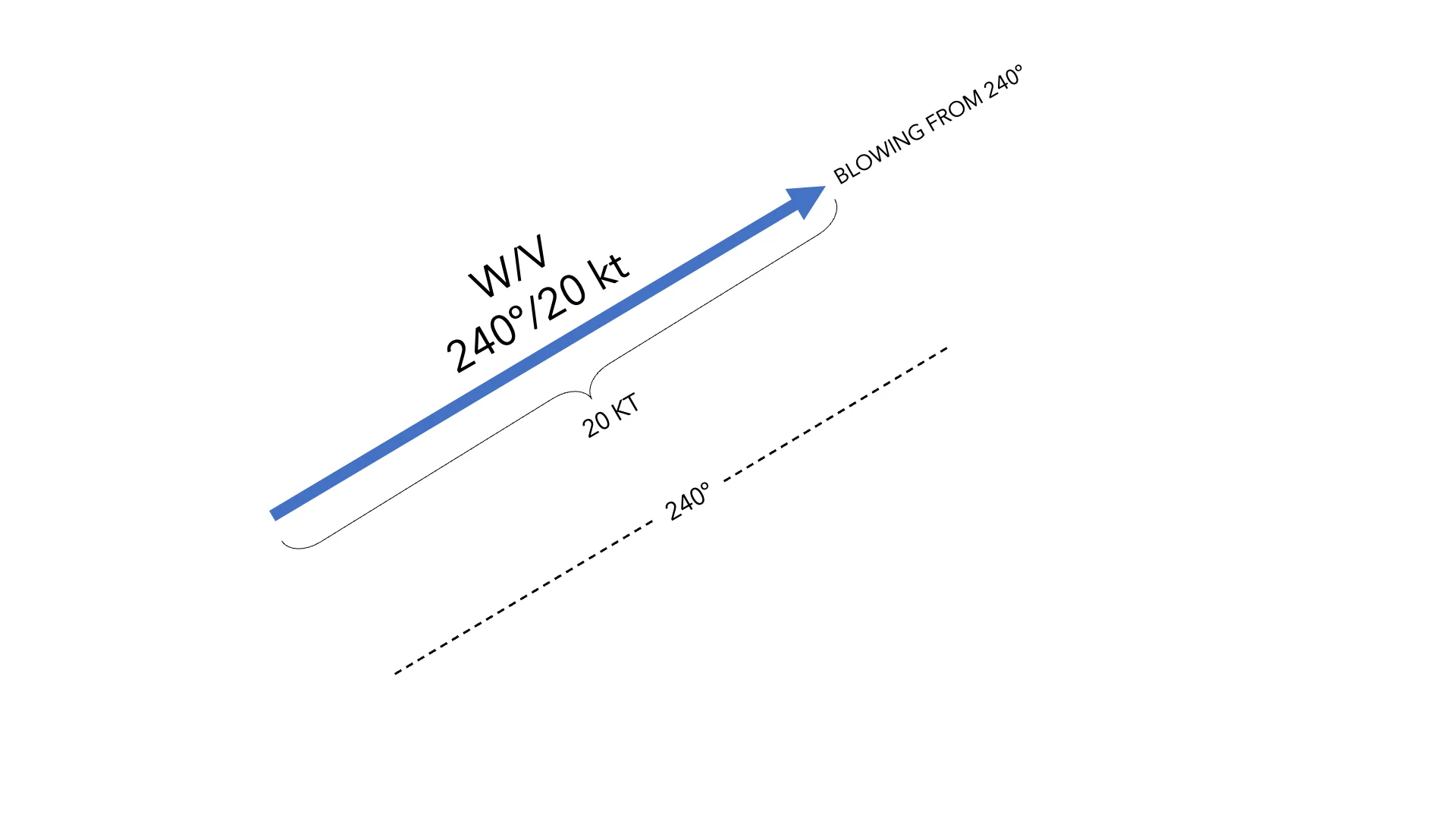
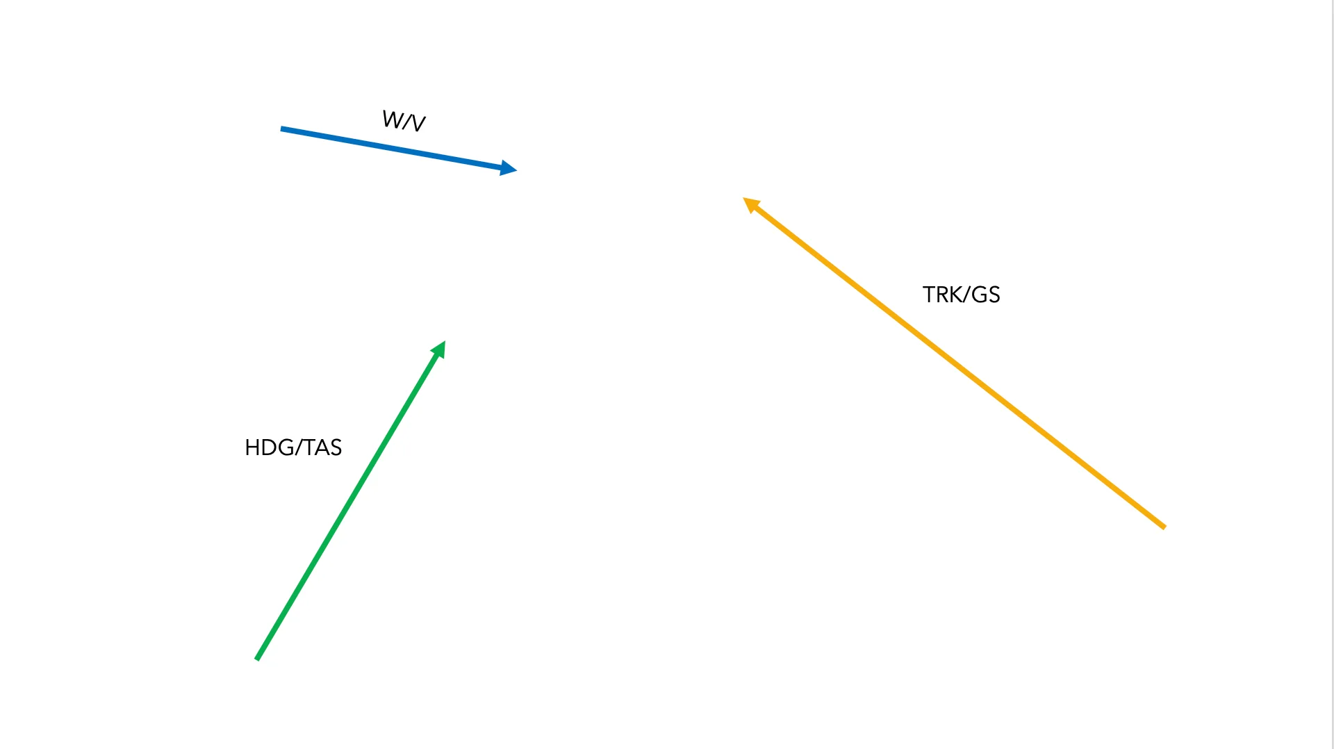
Let’s take wind as an example. It is not enough to say that there is a 20 kt wind, we also have to indicate where that wind comes from in order to fully define it. For example, the wind comes from 240º/20kt. In this way we have defined the direction and sense (it blows from 240º) along with the magnitude of the wind vector (20 kt). This pair of elements, wind and velocity, always goes together in order to be able to fully define the wind.
The same happens with the heading and true airspeed pair. They are two elements that always go together, indicating where the aircraft’s nose is pointing and at what speed the aircraft moves relative to the air.
The last indivisible pair we have left is track and groundspeed. These two elements indicate the imaginary line the aircraft paints over the ground together with the speed over that line. (Track is also known as course depending on whether we use American or British English).
DRIFT AND WIND CORRECTION ANGLE
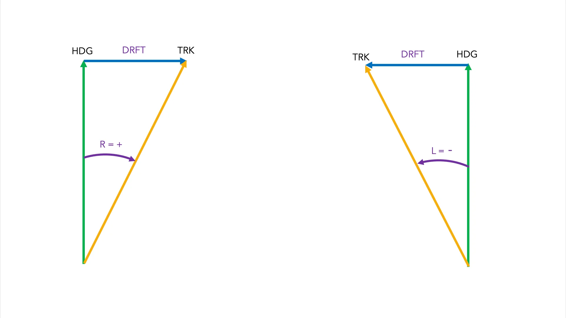
Drift is how much the wind pushes us sideways. Conceptually, you have to think that the wind “drifts” us from our HDG to our TRK. Always in this direction, again just in case: always from our HDG to our TRK. By definition, DRFT is the angular difference between these two values. For example:
HDG 100º / TRK 105º —> the wind drifted us 5º to the right (+5º)
HDG 334º / TRK 327º —> the wind drifted us 7º to the left (-7º)
The Wind Correction Angle is the correction we should apply in order to fly over the ground the HDG we initially wanted. In the first example (HDG 100º / TRK 105º) the wind has drifted us 5º to the right (+5º) if we want to compensate for the wind and fly a TRK of 100º, we should correct 5º to the left (-5º), obtaining a corrected HDG of 95º. By flying this corrected HDG of 95º, when the wind pushes now us sideways again, we will be flying a TRK of 100º over the ground.
DRFT and WCA have the same value but opposite sign. In all wind problems we will only work with DRFT. Therefore, if the question gives us the WCA, we will always convert it, without thinking twice, into DRFT.
VECTOR ADDITION
There are several ways to add vectors. One of them is using mathematics, although it would be a long and tedious process using pen and paper in a general navigation exam. Another option is graphical vector addition, which is much more visual.
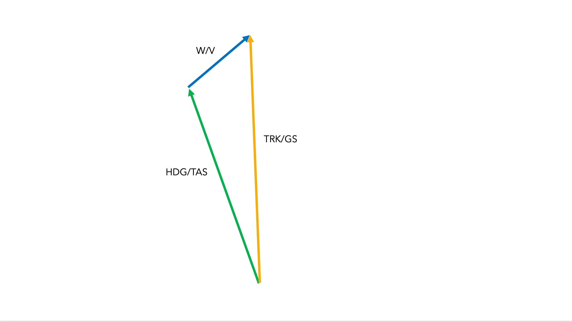
To add two vectors graphically, the tail of the second vector is drawn from the tip of the first. The resulting vector is drawn from the origin of the first vector to the tip of the second. As you can see in the image, this results in a triangle, hence the name “wind triangle”.
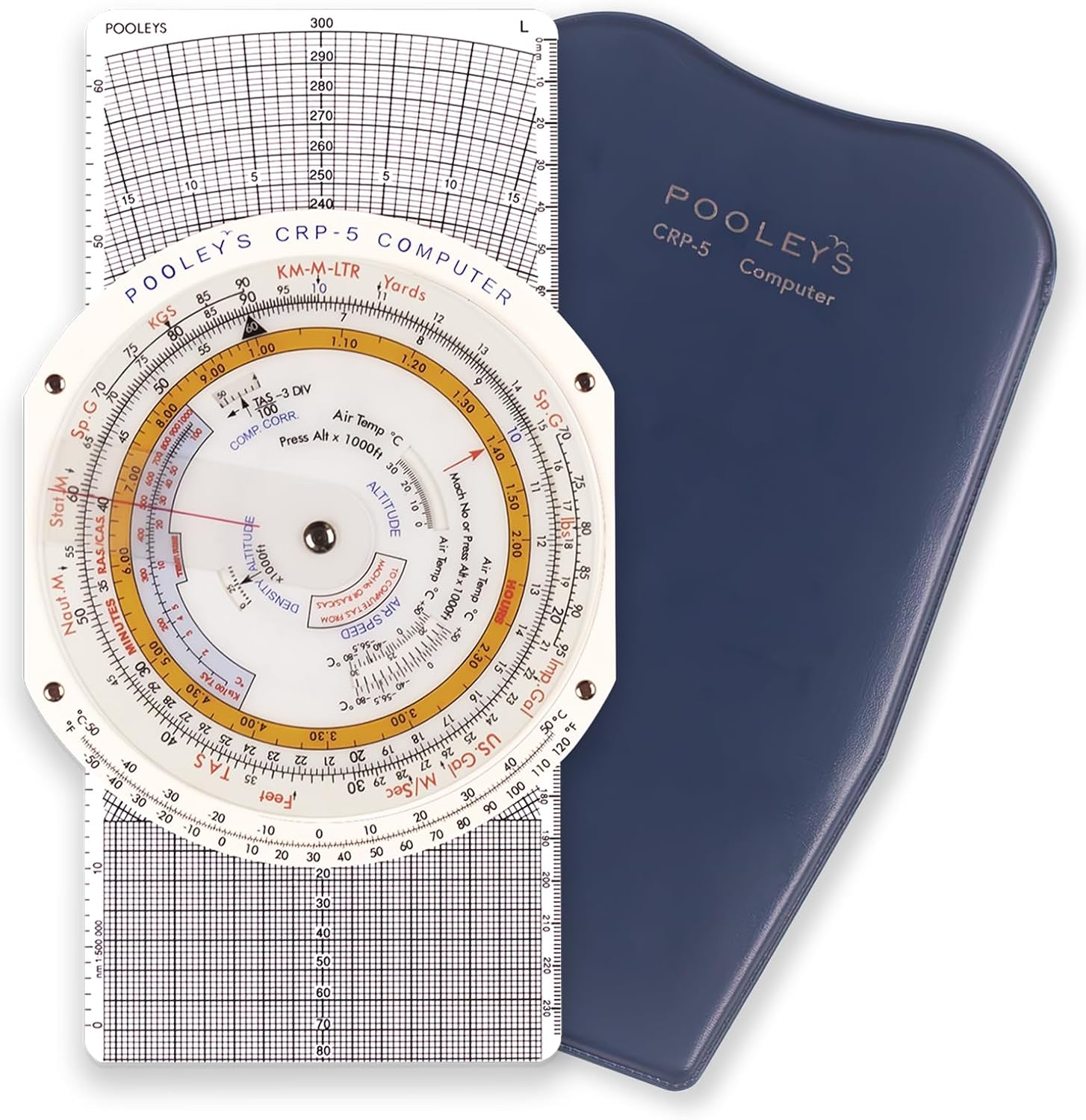
The CRP-5/E6B does exactly a graphical vector addition as described above. We show this graphical addition visually in the following video. Enjoy the magic (and the magician):
WIND PROBLEMS
Wind problems are always the same: they give us data about two vectors and we need to find data about the remaining vectors. In other words, the problem gives us 4 elements and asks us to calculate the remaining 2 elements. In general navigation exams there are three types* of wind problems. We are going to classify them as follows:
PROBLEM 1 - HDG/TAS, W/V —> Calculate TRK/GS
PROBLEM 2 - HDG/TAS, TRK/GS —> Calculate W/V
PROBLEM 3 - TRK/TAS, W/V —> Calculate HDG/GS
(*There is a fourth wind problem that is little known at CPL(A)/ATPL(A) levels which rarely appears in exams, only for the bravest: in this type of problem the aircraft flies two different VOR radials with two different headings and we need to work out the W/V.)
FINALLY NOW, SOLVING PROBLEMS
It is very complex to explain the use of the CRP-5/E6B using only words, so we have created a series of explanatory videos solving the three types of problems.
PROBLEM 1 - HDG/TAS, W/V —> Calculate TRK/GS
1 - Draw the W/V vector
2 - Place the center dot on the TAS
3 - Select the TH by rotating the circular scale
4 - Read the DRFT, TRK and GS values
PROBLEM 2 - HDG/TAS, TRK/GS —> Calculate W/V
1 - Place the center dot on the TAS
2 - Select the TH by rotating the circular scale
3 - Draw a point at the intersection of the DRFT with the GS arc.
4 - Move the circular scale until the point is positioned below, on the TAS line.
5 - Read the W/V
PROBLEM 3 - TRK/TAS, W/V —> Calculate HDG/GS
1 - Draw the W/V vector
2 - Place the center dot on the TAS
3 - Select the TRK by rotating the circular scale
4 - Adjust by moving the circular scale, the same number of degrees to the left or to the right as the drift value obtained.
5 - Read the TH and GS values
COMMON STUDENT MISTAKES
Here is a list of common mistakes I have seen in my students over all these years and that I hope you will never make.
- Not knowing which type of problem we are dealing with (1, 2 or 3)
- Knowing which type of problem we are dealing with but mixing up the steps between different problems.
- Knowing the steps of the problem but completing them in a different order.
- Despite doing everything mentioned above fine, not entering the data correctly on the CRP-5.
- Confusing the center dot with the TAS pen mark they have drawn.
- Not understanding the concept of positive or negative DRFT, not knowing when to add or subtract to obtain HDG or TRK. When in doubt, the best thing is to make a small sketch.
- Confusing 210º with 120º, 140º with 340º, etc.
- Solving the problem perfectly but reading the result incorrectly.
- Mixing units, for example True Heading with Magnetic Track. Before entering data on the CRP-5, make sure everything is in True or in Magnetic.
- Placing the center dot on the printed numbers on the CRP-5, not on the exact value. For example, if the TAS is 150 kt, placing the center dot at 152–154 kt.
- In problem type 2 (finding W/V), rotating the circular scale to put the drawn point above the center dot, remember it is always below the center dot.
One last piece of advice, probably the most valuable one and the one with which I have managed to help most students: during the exam, you will find answer options that are very close to each other. Never, never ever, read the answer options before starting to solve the problem. By doing so, our brain is unconsciously biased and tends to consider one of those options as the correct one. When we finish the exercise, if we do not get exactly any of the answers, it is easy to fall into the trap of choosing the most similar result, letting ourselves be carried away by that suggestion, and sometimes even "adjusting" the CRP-5 to make it fit. So, before starting to solve the problem, DO NOT READ the answers. If ultimately you do not obtain one of the answer options, my recommendation is clear: move on to the next question and come back later to solve it again from zero, with a clear mind.
NOTES FOR INSTRUCTORS AND SCHOOLS
I include this section with typical clarifications that many instructors have raised with me over all these years.
WHY THE CRP-5 AND NOT THE CR3 OR ANOTHER CIRCULAR CALCULATOR
Two reasons: accuracy and simplicity. As long as the point we draw with the pen/marker is small or thin enough, the CRP-5 offers an accuracy of +-2kt in speed and +-1º in direction. Circular calculators such as the CR3 start to give errors with high speeds or very small angles. In addition, the steps to follow on the CRP-5 are much easier to remember.
WHY THE CRP-5 AND NOT MATHEMATICS
Vectors are mathematical tools. The problem is that in 99% of the explanations I have attended, both as a student and as an instructor, students were not taught how to solve the problems using vectors, but rather using sine and cosine. In all the explanations I have been able to see, the modus operandi consisted of breaking down the wind vector into two components (head/tailwind and crosswind) to obtain a final vector. The mistake is that the combined effect of the wind vector on the direction of the resulting final vector is not taken into account. In other words, the “stretching” of the final vector produced by drift is not considered. This, although it seems unimportant, can under certain conditions lead to errors of +-9 kt and +-4º, all of this without even considering the decimals that we lose on the calculator when using sine and cosine with small angles, giving rise to small errors that keep accumulating until they become a large one at the end of the final result.
WHY DON’T WE EXPLAIN THE OTHER SIDE OF THE CRP-5
On the other side of the CRP-5 you can calculate density altitude, true altitude, TAS, Mach number, and perform unit conversions. To carry out these tasks I do strongly recommend using formulas because in this case they will be more accurate than the flight computer, as well as being faster and making fewer mistakes due to misreading the small numbers on the CRP-5 scales. Don’t you worry my fellow reader, I’m going to give you everything you need to succeed, so here are all the formulas, ordered one by one with colors:
True Altitude = Pressure Altitude +- (Temp correction of 4% of the height for every 10º ISA dev)
Density Altitude = Pressure Altitude +- (120 x ISA deviation)
MACH = TAS / LSS (LSS = 38.95 x √273+(T) (ºC))
TAS ≈ IAS + (2% IAS every 1,000 ft altitude)
ONE LAST MAGIC TRICK
I have always loved teaching and showing my students something valuable. Seeing how they walk into the classroom with some fear of the CRP-5 and finally leave with full confidence at the end of the lesson is a feeling I can't describe. I hope all of you feel the same, or at least somehow similar, after this reading.
Finally, I also think the best way to end any lesson is with a Grand Finale, one last magic trick. Therefore, I will leave you one last question:
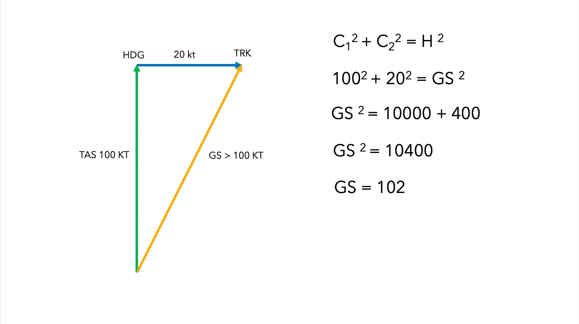
Without using the flight computer. Imagine we are flying with a HDG of 360º at a TAS of 100 kt. We have a full 20 kt crosswind from the left. What is the groundspeed of the aircraft?
99.999% of airline pilots will tell you that the GS is equal to the TAS of 100 kt because the wind is full crosswind, there is no headwind or tailwind component. But you, dear reader of this guide, you already know how to add vectors graphically, so you are among the few enlightened ones who will know the truth. And the truth is that the GS is greater than 100 kt. And if you don’t believe me, have a look at the diagram below and tell me: isn’t it true that the hypotenuse of a right triangle is greater than its legs? A magician never reveals his tricks, so I’ll leave you to reflect on this last discovery by yourself.
My work with you has come to an end. Good luck with your written exams. With all our love, the Private Pilot Exams team.